1.2 Data Format Standards
"Without standards, there is no interoperability; without interoperability, medical imaging is just data on isolated islands." —— The Foundation of Medical Informatics
Imagine this scenario: Patient Wang had a CT scan at Hospital A and received a CD. A few days later, he came to Hospital B seeking a second opinion, only to find that Hospital B's imaging system could not open the CD. Reluctantly, he had to undergo another scan at Hospital B, not only increasing costs but also exposing him to additional radiation.
This seemingly absurd scenario was the norm before medical imaging standardization. This chapter will take you through the evolution of medical imaging data format standards, with emphasis on the two core standards—DICOM and NIfTI—and how they solved the challenges of medical imaging data exchange and sharing.
📜 The Era of Chaos Before Standardization
Early Proprietary Formats
From the 1970s to the 1980s, medical imaging equipment manufacturers developed proprietary data formats independently. GE, Siemens, Philips, Toshiba, and other vendors each had their own format specifications, which were completely incompatible with each other.
This chaos created serious problems:
- Hospital Level: Images from different brands of equipment could not be viewed and managed in the same system
- Patient Level: Patients had to undergo repeat scans when transferring between hospitals, increasing costs and radiation exposure
- Research Level: Multi-center studies struggled to integrate imaging data from different hospitals
- Software Development Level: Third-party software needed to support dozens of formats, resulting in extremely high development costs
| Period | Format Status | Main Issues |
|---|---|---|
| 1970s-1980s | Proprietary format per vendor | Complete incompatibility, data silos |
| 1985-1988 | ACR-NEMA 1.0/2.0 | Point-to-point transmission only, lacking network capability |
| 1993 | DICOM 3.0 released | Era of standardization begins |
The Call for Standardization and Early Attempts
Facing this chaotic situation, the American College of Radiology (ACR) and the National Electrical Manufacturers Association (NEMA) began collaborating in 1983 to establish a unified medical imaging standard.
Early standardization attempts:
- 1985: ACR-NEMA 1.0 released, defining basic data format and point-to-point transmission protocol
- 1988: ACR-NEMA 2.0 released, improving data dictionary and command structure
Why did early standards fail?
- Only supported point-to-point direct connections, unable to adapt to networking trends
- Lacked a comprehensive information model, making it difficult to describe complex clinical scenarios
- No clear conformance testing standards, resulting in inconsistent vendor implementations
💡 Why is standardization so difficult?
Medical imaging standardization is not just a technical issue, but a process of balancing interests. Equipment manufacturers worry that open standards will weaken their market competitiveness, while hospitals and radiology departments desperately need interoperability. DICOM's success lies in finding a balance between technical standardization and commercial interests.
🏥 DICOM Standard—The Universal Language of Medical Imaging
The Birth of DICOM: From ACR-NEMA to DICOM 3.0
In 1993, after learning from the experience of the ACR-NEMA standard, DICOM 3.0 (Digital Imaging and Communications in Medicine) was officially released. This marked the beginning of a new era in medical imaging standardization.
Revolutionary breakthroughs of DICOM 3.0:
- Network transmission support: Based on TCP/IP protocol, adapting to the Internet era
- Object-oriented information model: Clearly describing the hierarchical relationships between patients, studies, series, and images
- Standardized service classes: Defining standard operations such as storage, query, and retrieval
- Vendor and device independent: Any vendor can implement the DICOM standard
🎯 The Revolutionary Significance of DICOM
DICOM is not just a file format, but a complete medical imaging information system standard. It defines data format, network communication protocol, service classes, conformance testing, and more, enabling seamless collaboration between equipment and systems from different vendors.
Core Architecture of DICOM
The core of the DICOM standard is the combination of Information Object Definitions (IOD) and Service Classes.
Information Object Definition (IOD)
IOD (Information Object Definition) defines the data structure for specific types of medical images. Each imaging modality has a corresponding IOD:
| IOD Type | Description | Typical Application |
|---|---|---|
| CT Image IOD | Data structure of CT images | CT scanning |
| MR Image IOD | Data structure of MRI images | MRI scanning |
| PET Image IOD | Data structure of PET images | PET scanning |
| Ultrasound Image IOD | Data structure of ultrasound images | Ultrasound examination |
| RT Structure Set IOD | Radiotherapy structure set | Radiotherapy planning |
| Presentation State IOD | Display state | Image annotation and measurement |
Service Classes
Service Classes define standard operations between DICOM systems:
| Service Class | Abbreviation | Function Description |
|---|---|---|
| Storage Service Class | C-STORE | Store images to PACS |
| Query/Retrieve Service Class | C-FIND / C-MOVE | Query and retrieve images |
| Worklist Service Class | MWL | Obtain examination worklist |
| Print Service Class | C-PRINT | Print images to film |
| Modality Performed Procedure Step | MPPS | Report examination execution status |
Service-Object Pair (SOP)
SOP (Service-Object Pair) is the combination of IOD and service class, representing a specific DICOM operation:
- SOP Class: Defines the object type and executable operations
- SOP Instance: A specific instance of the SOP Class
- SOP Class UID: Globally unique identifier, such as
1.2.840.10008.5.1.4.1.1.2(CT Image Storage)
Example: CT Image Storage SOP Class = CT Image IOD + Storage Service Class
Deep Analysis of DICOM File Structure
A standard DICOM file consists of the following parts:
File Composition
┌─────────────────────────────────────┐
│  File Preamble                      │  128 bytes, usually 0x00
├─────────────────────────────────────┤
│  DICOM Prefix                       │  4 bytes: "DICM"
├─────────────────────────────────────┤
│  File Meta Information              │  Transfer syntax, SOP Class UID, etc.
├─────────────────────────────────────┤
│  Data Set                           │  Actual image data and metadata
│  ├─ Patient Information             │
│  ├─ Study Information               │
│  ├─ Series Information              │
│  ├─ Image Information               │
│  └─ Pixel Data                      │
└─────────────────────────────────────┘Data Element
A DICOM dataset consists of a series of Data Elements, each containing:
- Tag: (Group, Element) format, such as
(0010,0010)representing patient name - Value Representation (VR): Data type
PN: Person NameDA: Date (YYYYMMDD)TM: Time (HHMMSS)UI: Unique IdentifierUS: Unsigned Short
- Value Length (VL): Data length
- Value Field: Actual data
Common DICOM Tags Quick Reference
| Tag | Name | VR | Description |
|---|---|---|---|
(0008,0018) | SOP Instance UID | UI | Image unique identifier |
(0008,0060) | Modality | CS | Imaging modality (CT/MR/PT, etc.) |
(0010,0010) | Patient Name | PN | Patient name |
(0010,0020) | Patient ID | LO | Patient ID |
(0010,0030) | Patient Birth Date | DA | Patient birth date |
(0010,0040) | Patient Sex | CS | Patient sex |
(0020,000D) | Study Instance UID | UI | Study unique identifier |
(0020,000E) | Series Instance UID | UI | Series unique identifier |
(0020,0013) | Instance Number | IS | Image number |
(0028,0010) | Rows | US | Image rows |
(0028,0011) | Columns | US | Image columns |
(0028,0030) | Pixel Spacing | DS | Pixel spacing (mm) |
(0028,0100) | Bits Allocated | US | Bits allocated per pixel |
(7FE0,0010) | Pixel Data | OW/OB | Pixel data |
⚠️ DICOM Tag Naming Rules
DICOM tags have special meanings in their Group numbers:
- Even Groups (such as 0008, 0010): Standard DICOM tags
- Odd Groups (such as 0009, 0011): Vendor private tags
- Group 0002: File meta information
- Group 7FE0: Pixel data
Private tags allow vendors to extend the DICOM standard, but may cause interoperability issues.
DICOM Hierarchical Structure: Patient-Study-Series-Instance
DICOM uses a four-level hierarchical structure to organize medical imaging data:
Patient
  └─ Study
       └─ Series
└─ Instance UML model of DICOM four-level hierarchical structure
Meaning of each level:
| Level | Description | Key UID | Example |
|---|---|---|---|
| Patient | All studies of a patient | Patient ID | All images of Zhang San |
| Study | All images from one visit | Study Instance UID | Hospitalization examination on January 15, 2024 |
| Series | All images from one scan | Series Instance UID | Chest CT plain scan sequence |
| Instance | Single image or object | SOP Instance UID | 50th layer CT image |
Practical application example:
- Patient "Zhang San" (Patient) was hospitalized on January 15, 2024 (Study)
- Underwent chest CT examination, including plain scan (Series 1) and enhanced scan (Series 2)
- Plain scan sequence contains 300 images (Instance 1-300)
📊 Why is hierarchical structure needed?
The hierarchical structure makes the organization and management of medical imaging data clearer:
- Patient level: Track the complete imaging history of a patient
- Study level: Associate all images from the same visit (CT, MRI, X-ray, etc.)
- Series level: Distinguish different scanning protocols (plain scan, enhanced, different sequences)
- Instance level: Precisely locate each image
This structure is also the basis for PACS system database design.
DICOM Transfer Syntax and Compression
Transfer Syntax defines the encoding method of DICOM data, including byte order (big-endian/little-endian) and whether compression is used.
Common Transfer Syntaxes
| Transfer Syntax | UID | Description | Application Scenario |
|---|---|---|---|
| Implicit VR Little Endian | 1.2.840.10008.1.2 | Implicit VR, little-endian | Default transfer syntax |
| Explicit VR Little Endian | 1.2.840.10008.1.2.1 | Explicit VR, little-endian | Most commonly used |
| Explicit VR Big Endian | 1.2.840.10008.1.2.2 | Explicit VR, big-endian | Rarely used |
| JPEG Baseline | 1.2.840.10008.1.2.4.50 | JPEG lossy compression | Archive storage |
| JPEG Lossless | 1.2.840.10008.1.2.4.70 | JPEG lossless compression | Diagnostic imaging |
| JPEG 2000 Lossless | 1.2.840.10008.1.2.4.90 | JPEG 2000 lossless | High-quality archive |
| RLE Lossless | 1.2.840.10008.1.2.5 | Run-length encoding lossless | Fast compression |
Lossy vs. Lossless Compression
📊 When to use lossy compression?
Lossless compression (recommended for):
- Diagnostic imaging: Need to preserve all details
- Radiotherapy planning: Precise dose calculation
- Research data: Quantitative analysis
Lossy compression (can be used for):
- Archive storage: Save storage space (compression ratio up to 10:1)
- Remote consultation: Reduce network transmission time
- Teaching images: Low detail requirements
Note: Many countries and regions' medical regulations require diagnostic imaging to use lossless compression or no compression.
🧠 NIfTI Format—The Standard for Neuroimaging
Background of NIfTI's Birth
Although DICOM achieved great success in clinical applications, in the research field, particularly in neuroimaging research, DICOM has some limitations:
Inconveniences of DICOM in research:
- Scattered files: A 3D volume is scattered across hundreds of DICOM files (one file per slice)
- Redundant metadata: Each file contains complete patient and study information
- Low read/write efficiency: Need to read and parse many files
- Unsuitable for batch processing: Complex script processing
Needs of the neuroimaging community:
- Simple file structure (single file storing 3D/4D data)
- Efficient read/write performance
- Clear spatial coordinate system
- Suitable for scripted batch processing
In 2004, the Neuroimaging Informatics Technology Initiative, funded by the National Institutes of Health (NIH), released the NIfTI-1 format, which quickly became the de facto standard for neuroimaging research.
NIfTI File Structure
NIfTI-1 Format
File extensions:
.nii: Single file format (file header + image data).hdr+.img: Dual file format (file header and image data separated).nii.gz: Compressed single file format (recommended)
File composition:
┌─────────────────────────────────────┐
│  NIfTI-1 Header                     │  348 bytes, containing all metadata
├─────────────────────────────────────┤
│  Extension (optional)               │  Extension information
├─────────────────────────────────────┤
│  Image Data                         │  Image data (can be multi-dimensional)
└─────────────────────────────────────┘Key Fields in NIfTI File Header
| Field Name | Type | Description |
|---|---|---|
sizeof_hdr | int | File header size (348 bytes) |
dim[8] | short | Image dimensions (up to 7 dimensions) |
datatype | short | Data type (uint8, int16, float32, etc.) |
bitpix | short | Bits per pixel |
pixdim[8] | float | Voxel size (mm) |
vox_offset | float | Image data start position |
scl_slope | float | Data scaling slope |
scl_inter | float | Data scaling intercept |
qform_code | short | Coordinate system method 1 (quaternion) |
sform_code | short | Coordinate system method 2 (affine matrix) |
descrip | char[80] | Data description |
NIfTI Coordinate System
NIfTI defines a clear spatial coordinate system, which is an important advantage over DICOM.
Two types of coordinates:
- Voxel Coordinates: (i, j, k), integer indices
- World Coordinates: (x, y, z), unit mm, relative to an anatomical reference point
Coordinate transformation methods:
NIfTI provides two methods to convert voxel coordinates to world coordinates:
Method 1 (qform): Rigid transformation based on quaternions
- Applicable to scanner coordinate system
- Contains only rotation and translation
Method 2 (sform): General affine transformation matrix
- Applicable to standard space (such as MNI space, Talairach space)
- Can include scaling, shearing, and other transformations
Affine transformation matrix:
[x]   [m11 m12 m13 m14] [i]
[y] = [m21 m22 m23 m24] [j]
[z]   [m31 m32 m33 m34] [k]
[1] [ 0 0 0 1] [1]💡 Why is the coordinate system so important?
In neuroimaging research, it is often necessary to:
- Registration: Align images from different time points or different patients
- Normalization: Convert individual images to standard space (such as MNI152)
- ROI analysis: Define regions of interest in standard space
A clear coordinate system makes these operations more accurate and reproducible.
NIfTI-2: Larger and More Flexible
In 2011, the NIfTI-2 format was released with major improvements including:
| Feature | NIfTI-1 | NIfTI-2 |
|---|---|---|
| File Header Size | 348 bytes | 540 bytes |
| Dimension Data Type | int16 | int64 |
| Maximum Image Size | 32,767 | 9,223,372,036,854,775,807 |
| Voxel Size Precision | float32 | float64 |
| File Extension | .nii | .nii (distinguished by magic string) |
NIfTI-2 is mainly used for ultra-large-scale imaging data (such as whole-brain high-resolution connectomics data).
📁 Other Common Medical Imaging Formats
In addition to DICOM and NIfTI, there are other formats in the medical imaging field, each with specific application scenarios.
Format Comparison Overview
| Format | File Extension | Main Purpose | Advantages | Disadvantages |
|---|---|---|---|---|
| DICOM | .dcm | Clinical imaging | Standardized, rich metadata, network transmission | Scattered files, complex |
| NIfTI | .nii, .nii.gz | Neuroimaging research | Simple, efficient, single file | Limited metadata |
| NRRD | .nrrd, .nhdr | 3D Slicer | Flexible, supports multiple data types | Non-standardized |
| MINC | .mnc | MNI brain atlas | Based on NetCDF/HDF5 | Limited usage |
| Analyze 7.5 | .hdr, .img | Legacy | Simple | Left-right ambiguity |
| MetaImage | .mhd, .raw | ITK toolkit | Simple, flexible | Non-standardized |
NRRD Format
Full name: Nearly Raw Raster Data
Characteristics:
- Simple ASCII file header + raw data
- Supports multiple data types and compression methods
- Widely used in open-source software like 3D Slicer
File structure:
.nhdr(file header) +.raw(data): Dual file.nrrd: Single file
MINC Format
Full name: Medical Image NetCDF
Characteristics:
- Based on NetCDF (Network Common Data Form)
- MINC2 based on HDF5
- Mainly used by the Montreal Neurological Institute (MNI) in Canada
- Suitable for multi-center research and brain atlas construction
Analyze 7.5 Format
Historical position: Predecessor of NIfTI
Problem: Left-right ambiguity (which led to the creation of NIfTI)
Current status: Replaced by NIfTI, but old data still uses this format
Other Formats
- GIPL (Guys Image Processing Lab): Early medical imaging format
- PAR/REC: Philips MRI proprietary format
- ECAT: PET-specific format
- MGH/MGZ: FreeSurfer software format
- BRIK/HEAD: AFNI software format
🔄 Necessity and Considerations of Format Conversion
Why Format Conversion is Needed
Typical workflow for medical imaging processing:
Clinical acquisition (DICOM) → Format conversion → Research analysis (NIfTI, etc.) → Result visualizationCommon scenarios for format conversion:
- Clinical to research: DICOM → NIfTI (most common)
- Software compatibility: Different software tools require different formats
- Data sharing: Standardized formats facilitate data sharing
- Storage optimization: Compressed formats save storage space
Common Format Conversion Tools
| Tool | Type | Main Function | Application Scenario |
|---|---|---|---|
| dcm2niix | Command line | DICOM → NIfTI | Batch conversion, most popular |
| pydicom | Python library | DICOM read/write | Scripted processing |
| nibabel | Python library | NIfTI/other format read/write | Python data analysis |
| SimpleITK | Python/C++ library | Multi-format conversion | Complex processing workflows |
| 3D Slicer | GUI | Multi-format conversion | Interactive operations |
| MRIcron | GUI | DICOM → NIfTI | Simple and easy to use |
💡 Tool Selection Recommendations
- Batch conversion: dcm2niix (fast, accurate)
- Python scripts: pydicom + nibabel
- Interactive operations: 3D Slicer or MRIcron
- Complex processing: SimpleITK
Detailed tool usage methods will be introduced in the next section (1.3 Common Open Source Tools).
Considerations for Format Conversion
1. Metadata Loss Issue
Problem: DICOM contains rich clinical metadata (patient information, examination parameters, device information, etc.), while NIfTI only retains basic image-related information.
Solution:
- Keep original DICOM files as backup
- Use tools (such as dcm2niix) to export metadata in JSON format
- Record the correspondence between DICOM and NIfTI in the database
2. Coordinate System Conversion
Problem: DICOM uses LPS coordinate system (Left-Posterior-Superior), while NIfTI typically uses RAS coordinate system (Right-Anterior-Superior).
Note:
- Ensure the conversion tool correctly handles coordinate system conversion
- Verify the image orientation after conversion (left-right, anterior-posterior, superior-inferior)
- Check if the affine matrix is correct
3. Multi-Series Processing
Problem: A DICOM Study may contain multiple Series (plain scan, enhanced, different sequences, etc.).
Strategy:
- Convert each Series separately
- Maintain clear file naming rules
- Record Series description and sequence number
4. Data Privacy and Anonymization
Problem: DICOM files contain patient privacy information (name, ID, birth date, etc.).
Anonymization requirements:
- Remove or replace patient name, ID
- Remove birth date or convert to age
- Retain necessary clinical information (sex, examination date, etc.)
- Comply with privacy regulations such as HIPAA, GDPR
⚠️ Data Privacy and Anonymization
Before sharing medical imaging data, anonymization must be performed:
- Must remove: Patient name, ID, address, phone number
- Optional removal: Birth date (can be converted to age), examination date (can be converted to relative date)
- Should retain: Sex, age, examination type, imaging parameters
Many countries and regions have strict legal requirements for medical data sharing, and violations can have serious consequences.
🌐 DICOM Network Transmission and PACS System
DICOM Network Protocol
DICOM not only defines file format but also defines network transmission protocol, enabling medical imaging devices and systems to communicate over the network.
Core Concepts
Application Entity (AE): DICOM network node
- AE Title: Node identifier (such as "CT_SCANNER_1")
- IP address and port: Network address (default port 104)
Association: Connection between two AEs
- Similar to TCP connection, but at application layer
- Requires negotiation of transfer syntax and SOP Class
DICOM Network Services
| Service Command | Function | Typical Application |
|---|---|---|
| C-ECHO | Test connection | DICOM Ping, verify network connectivity |
| C-STORE | Store images | Imaging device sends images to PACS |
| C-FIND | Query images | Workstation queries images in PACS |
| C-MOVE | Retrieve images | Workstation retrieves images from PACS |
| C-GET | Get images | Similar to C-MOVE, but returns images directly |
Introduction to PACS System
PACS (Picture Archiving and Communication System) is a hospital imaging archive and communication system, and is the core of modern hospital digital imaging management.
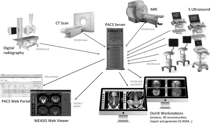 Architecture of a typical PACS system
PACS Composition
┌─────────────────────────────────────────────────────┐
│                    PACS System                      │
├─────────────────────────────────────────────────────┤
│  Imaging Acquisition Devices                        │
│  ├─ CT Scanner                                      │
│  ├─ MRI Scanner                                     │
│  ├─ X-ray Equipment                                 │
│  └─ Ultrasound Equipment                            │
├─────────────────────────────────────────────────────┤
│  PACS Server                                        │
│  ├─ Database Server (metadata)                      │
│  ├─ Storage Server (image data)                     │
│  └─ Web Server (remote access)                      │
├─────────────────────────────────────────────────────┤
│  Diagnostic Workstations                            │
│  ├─ Radiologist Workstation                         │
│  ├─ Clinician Viewing Terminal                      │
│  └─ Mobile Devices (tablets, phones)                │
└─────────────────────────────────────────────────────┘PACS Workflow
- Image Acquisition: CT/MRI and other devices complete scanning
- Image Transmission: Device sends images to PACS via DICOM C-STORE
- Image Storage: PACS server stores images and creates index
- Image Query: Doctor queries patient images via workstation (C-FIND)
- Image Retrieval: Workstation retrieves images from PACS (C-MOVE)
- Image Diagnosis: Doctor views images and issues report
- Image Archival: Long-term storage and backup
🏥 Digital Imaging Workflow in Modern Hospitals
The PACS system has completely changed the way hospitals manage images:
- Filmless: From traditional film to digital imaging
- Instant access: Doctors can view images from any terminal
- Remote consultation: Experts can view and diagnose remotely
- Long-term archival: Digital storage, never lost
- AI assistance: Provides data foundation for AI-assisted diagnosis
A large tertiary hospital's PACS system may process thousands of examinations per day, storing terabytes of imaging data.
🚀 Future Trends and Emerging Standards
DICOMweb: DICOM in the Web Era
Traditional DICOM network protocol is based on a custom protocol over TCP/IP, which has some limitations in modern web environments. DICOMweb is a new generation of DICOM service standard based on RESTful API.
Three major DICOMweb services:
- WADO-RS (Web Access to DICOM Objects): Retrieve DICOM objects via HTTP
- QIDO-RS (Query based on ID for DICOM Objects): Query DICOM objects via HTTP
- STOW-RS (Store Over the Web): Store DICOM objects via HTTP
Advantages:
- Cross-platform, cross-language
- Easy to integrate into web applications
- Cloud-friendly
- Support modern web technologies (JSON, OAuth, etc.)
FHIR and Medical Imaging
FHIR (Fast Healthcare Interoperability Resources) is a new generation of healthcare information exchange standard developed by HL7.
FHIR ImagingStudy Resource:
- Describes metadata of medical imaging studies
- Interoperable with DICOM
- Supports RESTful API
Complementarity of DICOM and FHIR:
- DICOM: Focuses on imaging data and imaging-specific workflows
- FHIR: Covers broader healthcare information (medical records, laboratory tests, prescriptions, etc.)
- Combined: Achieve complete healthcare information interoperability
Cloud Medical Imaging and AI
Future trends:
- Cloud PACS: Imaging data stored in the cloud, accessible anytime, anywhere
- AI-assisted diagnosis: Deep learning models directly integrated into PACS workflow
- Standardized datasets: Public standardized imaging datasets (such as TCIA, UK Biobank)
- Federated learning: Multi-center AI model training while protecting privacy
💡 Key Points Summary
Necessity of standardization: Early medical imaging formats were chaotic. The birth of the DICOM standard solved interoperability issues, enabling seamless collaboration between equipment and systems from different vendors.
Core architecture of DICOM: IOD (Information Object Definition) + Service Class = SOP (Service-Object Pair), which is the foundation of the DICOM standard.
DICOM file structure: File preamble + "DICM" prefix + file meta information + dataset (composed of tag-value pairs).
DICOM hierarchical structure: Four-level structure of Patient-Study-Series-Instance, clearly organizing medical imaging data.
Advantages of NIfTI: Simple, efficient, single file storage of 3D/4D data, clear spatial coordinate system, becoming the standard format for neuroimaging research.
Importance of format conversion: Conversion between clinical data (DICOM) and research data (NIfTI) is a common requirement in medical imaging processing.
Considerations for format conversion: Metadata loss, coordinate system conversion, multi-series processing, data privacy anonymization.
DICOM networking and PACS: DICOM is not just a file format, but a complete network communication protocol. PACS system is the core of modern hospital digital imaging management.
Future trends: DICOMweb, FHIR, cloud PACS, AI-assisted diagnosis—the development direction of medical imaging standardization and intelligence.
💡 Next Steps
Now you have learned about medical imaging data format standards. In the next section (1.3 Common Open Source Tools), we will explore how to use Python, ITK, SimpleITK, 3D Slicer, and other tools for medical imaging processing. In Chapter 2, we will learn medical imaging preprocessing techniques, including denoising, registration, segmentation, and other practical methods.